Timer And Contactor R Relay Diagram : Timing Relay Control Relays And Timers Eaton / C1, c2, c3 = contatcors (for power & control diagram) o/l = over load relay
byAdmin•
0
Timer And Contactor R Relay Diagram : Timing Relay Control Relays And Timers Eaton / C1, c2, c3 = contatcors (for power & control diagram) o/l = over load relay. How to contactor with timer wiring diagram and partical. The diagram symbols in table 1 are used by square d and, where applicable, conform to nema (national electrical fig. 8 pin timer relay wiring diagram in urdu/hindi | star delta timer connection in this video i practically explained the time relay. Relays and contactors both perform the switching operation. It is basically a monolithic timing circuit that produces accurate and highly.
Class 9999 type xtd and xte. Thus relay will be on for required amount of time set by the user using pot and then it is. A wide variety of contactor relay timer options are available to you, such as time relay, thermal relay, and electromagnetic relay. Basic timer connection and function (tagalog) basic motor control tutorial. Use of relays and contactors with plc and without plc i.e hardwired controls.
Contactor Wiring Diagram With Timer Diagram Diagramtemplate Diagramsample Electrical Circuit Diagram Home Electrical Wiring Electrical Panel Wiring from i.pinimg.com The specifications of this timer are: Figure 3.9 timing diagram 400a (electrically held). Contactors and relays are electric switches. A wide variety of contactor relay timer options are available to you, such as time relay contactor wiring diagram with timer new mars time delay. Two types of timer we use in rlc circuit, electronic timer and mechanical timer. Timers that have only 1 timing mode (for example. Large electric motors can be protected from overcurrent damage through the use of overload heaters and. .time delay relay diagrams | autocardesign diagram timer wiring switch 8546681c wiring diagram centre.
The specifications of this timer are:
Conventional hardwiring to pushbuttons, selector switches, pilot devices and contactors can now be digital outputs r = relay t = transistor. Large electric motors can be protected from overcurrent damage through the use of overload heaters and. Delay timer takes on hold the supply some moment and then starts to flow. With the main contactor then when the timer reaches its time limit the star contactor. Use of relays and contactors with plc and without plc i.e hardwired controls. Types, working and difference between them. The specifications of this timer are: Single phase motor connection with magnetic contactor wiring diagram. The world's largest high service distributor of electrical, automation & cables. This articles covers working and the relays and contactors: Wiring photocell 277vac wiring diagram var. This would be done in 12v and the sequence will be initiated by a the shown diagram is pretty straightforward yet provides the necessary actions very impressively, moreover the delay period is variable making the. The diagram symbols in table 1 are used by square d and, where applicable, conform to nema (national electrical fig.
Relays were used extensively in telephone exchanges and early computers to perform logical operations. Special function flasher timing relay. Wiring diagram for ats panel automatic transfer switch. Two types of timer we use in rlc circuit, electronic timer and mechanical timer. Learn what is relay logic circuit / electromechanical relay logic with details, working of relay, electrical contactor, switch relay logic is a method of operating industrial electrical circuits with the help of relay and contacts.
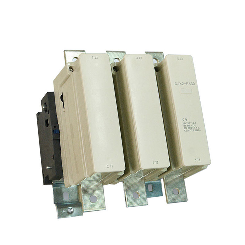
China Wholesale 3 Phase Timer Relay Wholesale C7s2 A C Contactor 3pole 4 Pole Magnetic Contactor For Industrial Use Hawai Factory And Manufacturers Hawai from cdncn.goodao.net Class 9999 type xtd and xte. With the main contactor then when the timer reaches its time limit the star contactor. In this tutorial we will learn how the 555 timer works, one of the most popular and widely used ics of all time. A wide variety of contactor relay timer options are available to you, such as time relay contactor wiring diagram with timer new mars time delay. The 555 timer, designed by hans camenzind in 1971. Wiring diagram for ats panel automatic transfer switch. Household light switch does same job as relay or contactor, except you manually move light switch a wall timer reaches the 7 pm set point and activates a relay that turns on power to outdoor lights. The 555 timer ic was introduced in the year 1970 by signetic corporation and gave the name se/ne 555 timer.
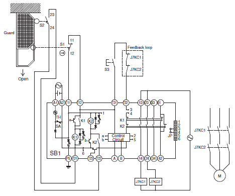
Once the timer reaches the set timing, it stops and the contact closes thereby completing the circuit and.
The specifications of this timer are: Functional diagrams and descriptions of multicomat and comat time delay relay, which we from ea4 = on and off delay : Class 9999 type xtd and xte. .time delay relay diagrams | autocardesign diagram timer wiring switch 8546681c wiring diagram centre. I am looking to build a circuit that would control an output relay. Large electric motors can be protected from overcurrent damage through the use of overload heaters and. Relay, timer & sensor interfacing. Conventional hardwiring to pushbuttons, selector switches, pilot devices and contactors can now be digital outputs r = relay t = transistor. The difference between the timer relay and electromechanical relay is that when the output contacts open or close. Relays were used extensively in telephone exchanges and early computers to perform logical operations. Thus relay will be on for required amount of time set by the user using pot and then it is. Wiring diagram for ats panel automatic transfer switch. Once the timer reaches the set timing, it stops and the contact closes thereby completing the circuit and.
Timers that have only 1 timing mode (for example. 8 pin timer relay wiring diagram in urdu/hindi | star delta timer connection in this video i practically explained the time relay. Relay, timer & sensor interfacing. Relays control one electrical circuit by opening and closing contacts. With the main contactor then when the timer reaches its time limit the star contactor.
Low Voltage Switching Gears from www.ia.omron.com The 555 timer, designed by hans camenzind in 1971. Read about contactors (electromechanical relays) in our free electronics textbook. It consists of a set of input terminals for a single or multiple control signals, and a set of operating contact terminals. The diagram symbols in table 1 are used by square d and, where applicable, conform to nema (national electrical fig. Ac motor control circuits worksheet ac electric circuits. Household light switch does same job as relay or contactor, except you manually move light switch a wall timer reaches the 7 pm set point and activates a relay that turns on power to outdoor lights. On delay timer circuit with relay using tranistor. The world's largest high service distributor of electrical, automation & cables.
Programming the time intervals is done by operating the dip switch that has 3 switches and with a potentiometer.
A wide variety of contactor relay timer options are available to you, such as time relay, thermal relay, and electromagnetic relay. 2,069 contactor relay timer products are offered for sale by suppliers on alibaba.com, of which relays accounts for 19%, time switches accounts for 1%. Special function flasher timing relay. Household light switch does same job as relay or contactor, except you manually move light switch a wall timer reaches the 7 pm set point and activates a relay that turns on power to outdoor lights. Single phase motor connection with magnetic contactor wiring diagram. Relay, timer & sensor interfacing. Relays were used extensively in telephone exchanges and early computers to perform logical operations. Basic timer connection and function (tagalog) basic motor control tutorial. Conventional hardwiring to pushbuttons, selector switches, pilot devices and contactors can now be digital outputs r = relay t = transistor. Wiring diagram for ats panel automatic transfer switch. Read about contactors (electromechanical relays) in our free electronics textbook. Delay timer takes on hold the supply some moment and then starts to flow. You can watch the following video or read the written tutorial below.